ENSURING THE QUALITY OF CONCRETE - NON DESTRUCTIVE TESTING
- akpremakumara

- May 6, 2021
- 8 min read
Updated: May 6, 2021
#CivilEngineering #ConcreteQuality #Reboundhammertest #UPVTest #Rectifications #Engineer #Innovation #CubeTesting
Source - Samhitha Innovations
What if Your Cube Strength Results, Fails ?
What if your cube tests results did not give out the desired output? Even if occurrences of higher strengths than what is required, are neglected often, records of low strengths or higher deviations among an unique sample set, can not be dealt in a similar manner, due to the risen risks of significant failures.
To gain a thorough understanding on established techniques on identifying failed concrete cube tests, please follow the earlier article of 'Ensuring the Quality of Concrete - Cube Testing'.
Apart from the failure pattern, a summary of detecting a failed set of cube samples on strength and deviation, as to be followed.


Why the Urgency for Non Destructive Testing Methods ?
Failed test cube results do not always imply that, the concreted location have not achieved the desired properties. During the casting of the cubes, a general hypothesis is followed, assuming that the casted cube and the concreted location have been governed by the same governing facets, which is far from the veracious conditions, most of the time. Hence, a high possibility of having deviated strength and other physical properties could be available, between concreted location and the cube test results.
In such a scenario, the obtainable properties at the concreted location should be assessed in a manner which, such procedure to deliver a impact of minimum, on the assessed element, addressing the possibility of the element having reached the desired requirements.
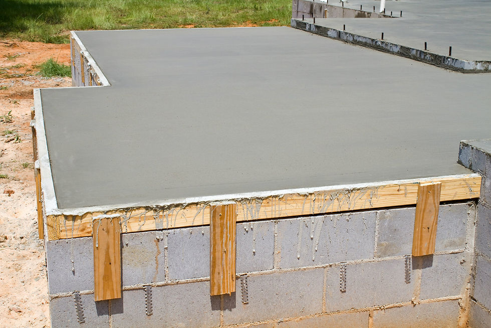
Source - Concreteconstruction.net
Any non destructive test method adapted in general practices, is unable to made specific strength value on the considered element, since they do not solely asses representative structural samples nor destructive stresses. Nonetheless many studies have instituted that specific tests measuring properties, such as Dynamic Young's Modulus, Modulus of Elasticity near the Surface, Consistency, etc. in concrete, can deliver a reliable assessment on the considered Element, hence practiced vastly amongst the industry.
In the following chapters, common non destructives tests, conducted on the general site conditions will be illustrated.
1. Rebound Hammer Test
Rebound Hammer Test, also known as Schmidt Hammer Test is a vastly adapted test technique which asses the surface of a concrete texture. Rebound Hammer apparatus contains a spring loaded with a steel hammer, which gives a number (Rebound Index) upon implementation, with respect to the hardness of the impacted surface with the influenced mass.
Considering the operation of the Rebound Hammer, once the spring loader hammer releases the stored energy upon the impacted surface, part of the energy get absorbed by the element prorogating mechanical waves, while the remaining energy causes the hammer to rebound, which represented as the result - Rebound Index.

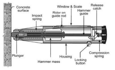
Rebound Hammer Apparatus (Source - Spectro.in)
Procedure
1. Clean the concrete surface achieving a dry and a smooth exterior. (No loose particles should be present.)
2. Calibrate the Apparatus. (Checked against Test Anvil - 5000 N/mm2)

3. Position the hammer right angles to the surface of the measuring element. (Make sure to place the hammer at least 20mm away from edges of the element or discontinuities)
4. Release the hammer and take the reading and repeat for at least 6 times for more accurate result.
5. Take the average on the repeated results.
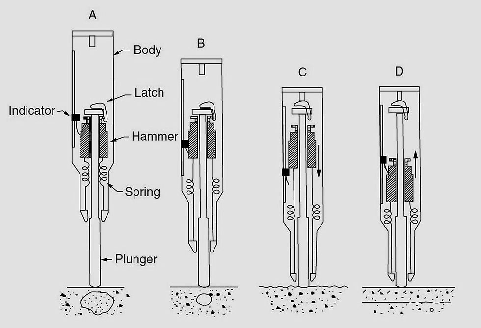
Operation of Rebound Hammer Apparatus (Source - civilblog.org)
Implementation of Results
The correlation between the rebound hammer results and the compressive strength of the concrete is achieved by conducting the test on cubes(150 mm a side) which assessed using the compressive strength apparatus as well.
Such interpretations under IS: 13311(2)-1992 as to be followed,

The results from rebound hammer test is estimated to have a deviation of +25% or -25% upon the actual, hence its is always encouraged to establish a correlation between compressive strength of cubes and rebound index, for the considered project prior to the implementation.
Advantages and Disadvantages

Modern Rebound Hammer Apparatus (Source - azom.com)
Advantages
Convenient and simple upon utilization.
Cost Effective (Initial and Operational Costs)
Repetition is undemanding.
Machine can be calibrated to give the compressive index with Rebound Index.
Can be conducted on smaller elements and at difficult places.

Different Positions of Operation of Rebound Hammer Apparatus (Source - constructor.org)
Disadvantages
Results are localized.
Apparatus needs to be cleaned, regularly.
Detection of Flows tends to be difficult.
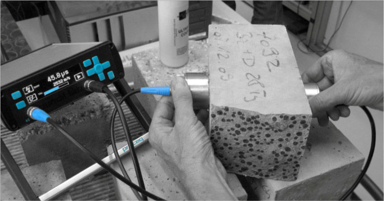
2. Ultrasonic Pulse Velocity Test (UPV Test)
Ultrasonic pulse velocity test is also a vast practice adapted in construction industry, to gain an essence of the
Quality
Homogeneity
Integrity
of a concrete element, efficiently.
By the apparatus, Pulse velocity in the considered element, of a induced pulse of 50-54 kHz, is measured by connecting transducers to end surfaces of the element.

Modern Ultrasonic Pulse Tester (Source - indiamart.com)
In early utilizations of this apparatus, the wave was generated using the impact by a hammer which now being modernized with transducers, yet the principles remain same. In operation , the element meets with 3 different wave forms, which are
P Wave (Longitudinal/Compressional) - induced along with the travel direction.
S Wave (Shear) - travels in right angles to the travel direction.
Rayleigh Wave - Travels in the surface, in 'retrograde ellipse' formation - One component travels normal to the surface while other is in the travel direction.
Procedure
1. Calibrate the tester using the reference. (From the reference bar)
2. Clean up the surface of the selection positions, to achieve a smooth surface.(Troweled surfaces are not encouraged to be tested against)
3. Position the transmitter and the receiver in the prepared surfaces with a coupling medium. (Encouraged Couplants - Petroleum jelly, Grease, Soft soap and Kaolin/Glycerol paste)
There are 3 different ways to position the transmitter and the receiver on the element, depending on the wave form to be measured, which illustrated in figure 1.

Figure 1- Positioning of Transducers (Source - BS 1881-203: 1986 )
In lateral measurements only(Semi Direct Transmission), the shape and size of the specimen/element plays interference on the frequency of transmission, transferred by the instrument. If the minimum lateral distance is not to be maintained, the properties of the wave will change which will interpret deviated resultant times, from the actual. (Table 2)

Table 2 - Minimum allowed lateral dimension accordance with transducer frequency and UPV Value (Source - BS 1881-203: 1986 )
4. Select the relevant micro second range compared to the path length, (recommended 0.1 micro second range) and generate the pulse using the apparatus, and hold still until the reading on the screen appears steady.
5. Then observe the time taken for the travel of the considered wave form and calculate the pulse velocity accordance with the following formula.

Interpretation of Results
Concrete Quality
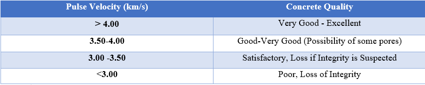
Source - constructor.org
Since concrete is a multi phase material, many constituents play vital roles in determining the Ultrasonic Pulse Velocity, so as the moisture content of the element. Unlike any other constituent, moisture content remains to be highly susceptible to outdoor environment, and specifically to the temperature too. Hence BS 1881-203: 1986, have addressed the changes have to be made in assessing the UPV value, in accordance with moisture content and temperature, which is illustrated in Table 3.

Table 3 - Correction Values to UPC accordance with temperature and moisture content (Source - BS 1881-203: 1986)
Concrete Uniformity
In general, the pulse velocity show fluctuations (Figure 2) when the medium is showing heterogenic properties. So analyzing the velocity changes on an element would provide an essential idea about the uniformity of the concrete as well.
In a large element, usually a 1m grid is utilized to asses the uniformity, however when the an element of smaller size is considered, the mesh/grid has to get finer, for more accurate information. If the path length could be kept constant for all the grid points, measuring time would be sufficient instead of calculating the UPV.
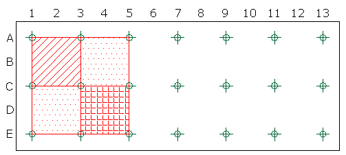
Sample grid for a UPV Test (Source - researchgate.com)
When the grid points are sufficient to be considered as a representative sample, statistical methods can also be adapted and parameters such as standard deviation, coefficient of variation can be interpreted to express the uniformity of the measured concrete. Not to mention such statistical results will allow for a comparison platform, but only for elements containing same dimensions.
Determination of Cracks
When the projected length of void/crack is,
Greater than the width of transducers and
Greater than the wavelength of the used sonic wave,
the induced wave tends to travel around the periphery of the crack which will take more time compared to an uncracked concrete potion in the same element. (Figure 2)

Figure 2 - Behavior of the Sonic wave (Uncracked, Non-Uniform and Cracked) (Source - slideshare.net)
However, process of identification of cracks using ultrasonic pulse velocity results, should only be conducted by an expert having sufficient field experience, due to the complexity of analysis. Every so often,
Occasions where cracked faces being hold closely by compression forces or
Marine environments, having cracks filled with saline water,
do not show much significant output/deviation in digital equipment, where such cracks need to be assessed with attenuation of waves, which is visible only to trained eyes. Such analyses could also implemented on finding the depth of the crack as well through a series of equations which can be referred in BS 1881-203: 1986.
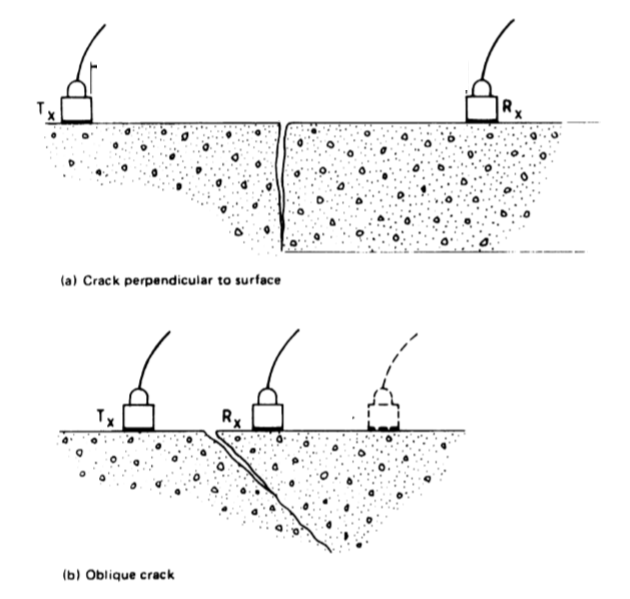
Arrangement of Transducers in measuring depths of different cracks (Source - BS 1881-203: 1986.)
Dynamic Young Modulus of Concrete
Using the results from Ultra Sonic Pulse Velocity and operational constants of the Electronic Pulse Generator, the Dynamic Young Modulus and the Poisson's Ratio of concrete, can be determined using following equations based on BS 1881-203: 1986.

Locating Portions Susceptible to Corrosion in Concrete
Incorporated with results from the rebound hammer test, the UPV results can be utilized, to identify portions prone to corrosion, which is illustrated in the following Table. (Table 4)
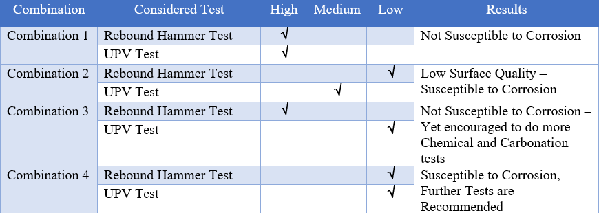
Table 4 - Locating Portions Susceptible to Corrosion (Source - Constructor.org)
Influence of Reinforcement in Test Results
The velocity of pulse waves utilized in UPV Test tend to travel twice the speed in Steel, than in plain concrete, hence its advisable to mitigate the vicinity of reinforcements, as much as possible, for accurate results on concrete quality. The General site practice is to utilize a Cover Meter to locate positions of embedded reinforcements and, to mitigate them in selecting the 'path' for the test.
Occasions which do not allow the mitigation, certain correction factors need to be adapted in determining the pulse velocity, depending on the r/f arrangement and physical factors, which is deliberated under BS 1881-203: 1986. for further references.
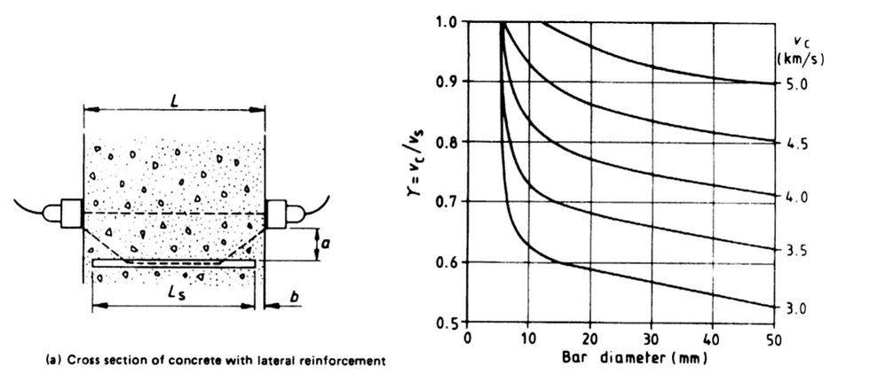
Influence of R/f in UPV Results (Arrangement - Lateral Reinforcements) (Source - BS 1881-203: 1986.)

Influence of R/f in UPV Results (Arrangement - Longitudinal Reinforcements) (Source - BS 1881-203: 1986.)
Conclusion
Ensuring the quality of the concrete is essential in any construction, for output to be durable, stable and functionable during its operational period. Hence continuous and regular testing methodologies need to adapted during the construction stages of a project. However initial testing methods such as Cube Testing could present insufficient strength properties for the considered poured potion. Since these tests being conducted under a general hypothesis of having similar governing properties in both location, which is not accurate all the time, such occasions with failed results, the poured element need to be assessed for the most accurate interpretations.
Usually the strength of the concrete is measured accordance with destructive tests, which is not ideal in a poured element, since damaging an element for a sample is not encouraged, until it becomes the remaining viable option. Hence Non Destructive Tests such as Rebound Hammer Test and Ultrasonic Pulse Velocity Tests proves to be vital in determining concrete strength and quality, without damaging the element.
What happens if these tests also show insufficient strength and quality sequel. Then the construction party has no option rather than proceed for a destructive tests with samples collected from the considered element, such as Core Cutter Test, Which will be deliberated in a future Article.
***(Content of this article is protected under intellectual property Act No.36, 2003 - Sri Lanka. Copying, Reproducing or Extracting any part of this publication is strictly prohibited without the consent of the author.) ***


Comments